How to make simple Variable HIGH VOLTAGE Power Supply
2025-12-15 | By Mirko Pavleski
License: General Public License Analog Arduino
A high-voltage power supply is usually understood as a device that is capable of generating a voltage of several kilovolts, or even tens and hundreds of kilovolts. Most often, these power supplies give a certain voltage at their output. When experimenting with high voltages, we almost always need a variable value of the generated high voltage. There are several ways to achieve this, and in this project, I will try to implement and explain all of these ways in one device. Of course, I will try to make the device as simple as possible and, at the same time, not use expensive and difficult-to-find components.
SAFETY NOTE: Please do not attempt to recreate the experiments shown on this video unless you are familiar with high-voltage safety techniques! Direct current even above 60V may be lethal, even when the AC supply voltage has been disconnected due to the stored energy in the capacitors. Be very careful!!!
Generally, such a device consists of three separate parts:
- An input source of DC voltage (Usually a voltage of 10 to 60 volts and the ability to provide a current of 3A or more)
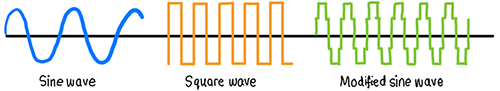
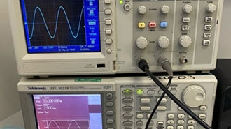
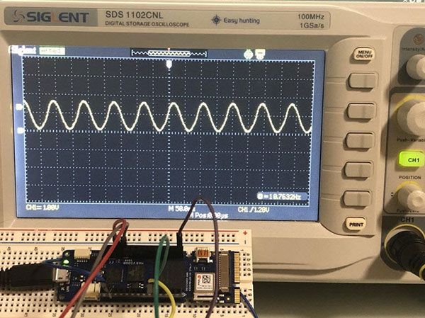
- Then there is the main part, which is a high-voltage generator, or rather a driver for driving an HV transformer. It is a generator of rectangular signals with a certain frequency and duty cycle at the output of which there is a power MOSFET mounted on a large heat sink.
- And a high-voltage (flyback) transformer that generates the high voltage, which can be DC or AC.
In this project, I will focus most of my attention on making the driver circuit, which is actually the most complex to make. Let me start by describing the components individually.
- The heart of the driver circuit is an inexpensive square wave generator with adjustable frequency and duty cycle. This incredibly useful—I also call it magical—module is responsible for the stability and versatility of the entire circuit.
- The signal output of the generator has a potentiometer with which the amplitude of the generated signal can be continuously regulated.
- At the input side of the low-voltage source, there is an automatic fuse that trips in the event of a driver failure, most likely a burnout of the MOSFETs.
- And a few optional components that serve us for better monitoring of the device, which are this small voltammeter at the input, as well as an analog instrument for an approximate representation of the value of the output high voltage.
Now let's see how the device works in real conditions. At the input, I initially bring 12V and a current limited to 2A. At the output, I connected a flyback transformer from an old CRT monitor, on whose core I wound a primary consisting of 7 windings. Here, we need to experiment because in different models of transformers, the number of windings to achieve the highest efficiency is different. Now we activate the power supply, and a spark should appear on the secondary of the transformer. If there is no spark or it is very small, and the current does not exceed 2A (the protection does not turn on), we need to choose a different frequency and duty cycle of the generator. In fact, the duty cycle should be in the range of 30 to 45% and the frequency from 15 to 30 kilohertz, depending on the model of the HV transformer. In this particular case, for this transformer, the hotspot for best efficiency is a frequency around 15 KHz and a duty cycle of 36%.
Next, about the ways for continuous, precise regulation of the high-voltage output.
- The first and simplest way is, as you probably guessed, by changing the input voltage to power the device. In this case, the generator parameters remain the same, the potentiometer is at maximum, and only the input voltage changes. We will roughly approximate the voltage value by the length of the spark on the secondary of the transformer. A spark starts to be generated even at less than 6V, which is a sign of good tuning and efficiency of the entire system. With increasing the input voltage, the length of the generated spark, i.e., the HV voltage, also increases.
If we have the opportunity, instead of a laboratory rectifier that contains a switching circuit and is sensitive to high-frequency parasitic signals, it is best to use a standard transformer with a classic rectifier on which we install a Variac. By regulating the primary voltage through the variac, we also control the value of the HV voltage.
- The next, slightly more crude way to regulate is by changing the duty cycle value. In this case, we set the input voltage to the highest previously determined level and change the duty cycle from 5% to about 40%.
- And finally, with a potentiometer at the output of the signal generator that changes the amplitude of the rectangular signal. By moving the potentiometer clockwise, the output high voltage increases proportionally.
Next, I will repeat the last case, but with different transformers and with a different number of primary windings.
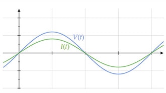
I thought it would be ideal if we had some kind of visual approximation of the value of the high voltage. So I tried to make a cheap monitor with a small analog instrument. Immediately next to the primary of the HV transformer, I wound several turns of insulated wire with a diameter of about 0.5mm, and then through a rectifier and a 5-kilohm trimmer potentiometer, I brought the ends to the analog meter in my case, with a range of 0 to 5 volts. The original primary winding, when working, creates a magnetic flux through the core, whereby the voltage induced in the secondary winding and this additional feedback winding is proportional to the strength of this magnetic flux.
In this way, by measuring the voltage generated on the feedback winding, we relatively accurately determine the voltage induced in the secondary winding, that is, the HV. I don't have a commercial instrument or probe, so I can't calibrate this little gauge, but at least I have some rough idea of the voltage level. This method has many advantages as a safety measure because there is no direct connection to the HV side, no HV resistors needed, and it works for AC or pulsed DC
And finally, a short conclusion: In this project, I built a simple yet effective variable high voltage power supply using affordable components, offering precise control for high-voltage experiments. Tune the frequency, duty cycle, or input voltage to achieve the desired output, making this device a versatile tool for any electronics enthusiast.
SAFETY NOTE: Please do not attempt to recreate the experiments shown on this video unless you are familiar with high-voltage safety techniques! Direct current even above 60V may be lethal, even when the AC supply voltage has been disconnected due to the stored energy in the capacitors. I have no responsibility for any hazards caused by the circuit. Be very careful!!!