Scheme It
Introduction
Schematic Drawings

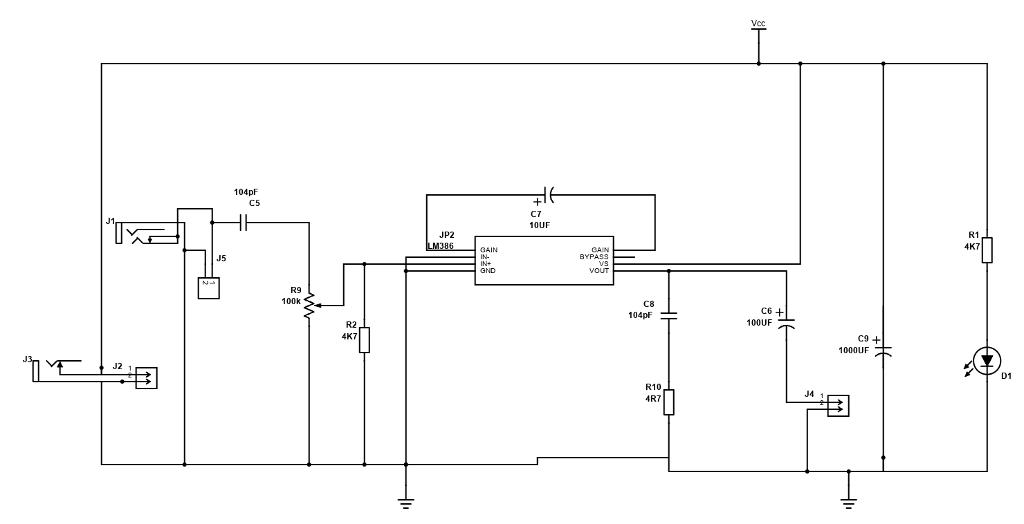
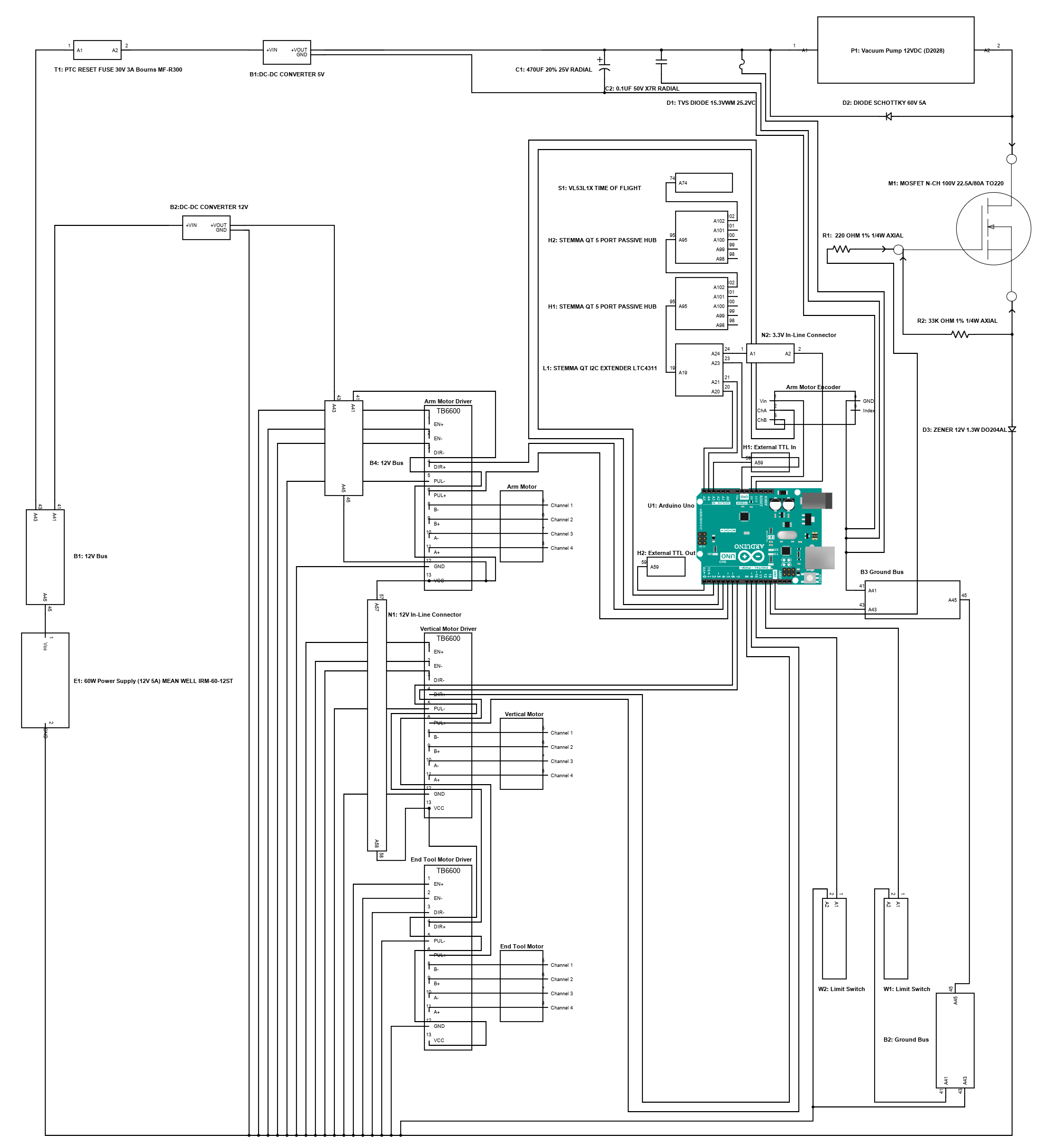
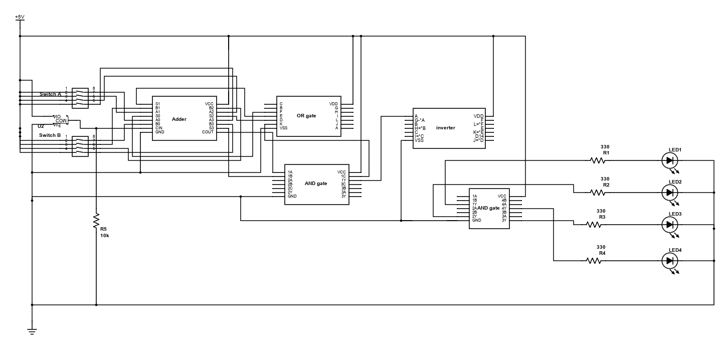
Use schematic symbols to layout the components of your circuit and make electrical connections. With symbols ranging from amplifiers to vacuum tubes, as well as the ability to build custom symbols, you are able to design nearly any circuit. Access to DigiKey's extensive part database also allows you to browse and assign orderable part numbers.
Diagram Building

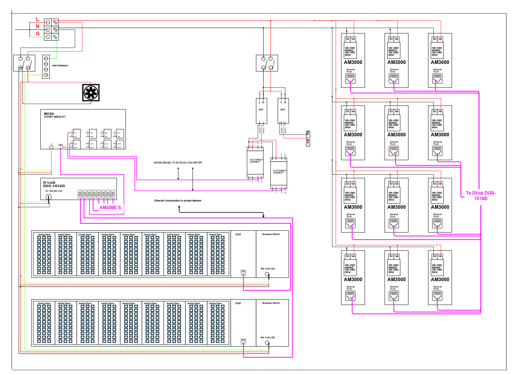
Use the system blocks to refine your idea at a conceptual level. The higher-level components are there to help you plan out the broader intentions of your idea. This powerful block chain library allows you to quickly layout the function of circuit. Once your design is ready, save and share with your colleagues.
Flow Chart Creation

The flow chart creation option will help transition your concept to a design. Use the library of arrows, shapes, UML symbols, and more to sort out the flow and annotate each stage. Insert a textbox, math function/formula, image, or link to help illustrate the objectives and make your plan easy to follow.
Projects
Refine Search
DATE RANGE
Arc Generator
2026-02-04 10:18:49
-
Cap voltage barely sags
-
Peak current high and instantaneous
-
Plasma forms but does not fully expand
-
MOSFET stays in switching-dominant regime (low heat)
-
Electrodes see minimal thermal load per pulse
Behavior
-
Sharp “impact” character
-
Distinct, snappy, discrete hits
-
No lingering arc
-
Sound profile: crisp crack, no sustain
Use when
-
You want maximum control over thermal load
-
You want clearly separated pulses
-
You want strong per-event effects without continuous heating
This is the high-peak-power, low-average-power mode.
2. Longer pulses (hundreds of µs → few ms)
Electrical reality
-
Cap voltage drops substantially within the pulse
-
Arc becomes fully established
-
Plasma column expands
-
MOSFET is in conduction regime (major heating)
-
Electrodes accumulate thermal load rapidly
Behavior
-
Looks and sounds like a short “burst” or mini-arc
-
More luminous, more sustained plasma
-
Per-pulse energy feels heavier and more massive
-
Not as “snappy,” more “burn-like”
Use when
-
You want visibly sustained events
-
Peak power is less important than overall arc duration
-
You accept higher thermal load per pulse
This is the lower-peak-power, higher-average-power mode.
3. Repetition rate determines how events stack over time
Low repetition rate (<1–3 Hz)
-
Each pulse is isolated
-
System resets thermally
-
You only care about single-pulse behavior
-
Mechanical/audible events are totally distinct
Use for: single shots, demonstrations, high-energy hits without cumulative heating.
Moderate repetition (5–30 Hz)
-
Feels rhythmic: “ticks,” “strobe”
-
Average heating becomes relevant
-
Component temperature ramps over time
-
Pulses remain distinguishable
Use for: stable repetitive operation where events need to be counted or perceived individually.
High repetition (50–200+ Hz)
-
Individual pulses blur together
-
Acoustic signature becomes buzzing or continuous
-
Average power dominates everything
-
Thermal limits become the governing constraint
-
Discharge may transition into quasi-continuous arc behavior if pulse width is long enough
Use for: continuous-effect systems, but requires tight thermal management.
4. The 3D design space is real and fundamental
Think of operation as a coordinate:
-
X-axis = pulse width (short → long)
-
Y-axis = repetition rate (low → high)
Each region behaves like:
Bottom-left: short, low-rate
-
Max peak impact
-
Zero cumulative heating
-
Sharp, isolated events
Top-left: short, high-rate
-
Buzzing, strobing
-
Peak power preserved
-
Average heating rises sharply
Bottom-right: long, low-rate
-
Heavy, dense, slow pulses
-
Full plasma events with time to cool
-
High per-pulse thermal load but safe average
Top-right: long, high-rate
-
Nearly continuous discharge
-
Arc-like behavior
-
Thermal limits dominate
-
Highest component/electrode stress
This grid is the actual map you’re working inside.
5. Practical way to choose operating point
Define three things:
-
Character of a single pulse
Sharp hit vs sustained burst -
How the sequence should feel over time
Isolated vs strobing vs continuous -
How much thermal budget you’re willing to spend
Low vs moderate vs high average load
Once those factors are chosen, the pulse width and repetition rate fall out automatically.

ABX00162-Ardunio-One-Q
2025-10-31 15:22:21
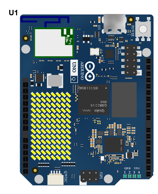
UNO Q Microcontroller Board
Arduino microcontroller boards provide advanced features and versatile applications for modern electronics
 The Arduino UNO Q is a high-performance, hybrid, single-board computer and microcontroller development board that redefines performance and versatility. Featuring cutting-edge USB Type-C® connectivity and built on the renowned UNO form factor, the UNO Q is designed to elevate projects. Equipped with a Linux Debian-capable MPU and a real-time microcontroller, this board is perfect for advanced applications in AI, computer vision, IoT, robotics, and industrial sectors.
The Arduino UNO Q seamlessly integrates with the Arduino App Lab development environment, empowering users to create groundbreaking applications across microcontrollers, embedded Linux, and edge AI. With its user-friendly examples and expandable capabilities through modular bricks, this powerful tool simplifies deployment with built-in orchestration. It helps users quickly and efficiently turn innovative ideas into reality.
Features
- Hybrid intelligence: combines Linux and real-time MCU control on a single board for smart, responsive, edge-aware applications
- Simplified development experience: App Lab offers prebuilt examples, intuitive building blocks (bricks), and scalable deployment with transparent orchestration of software and containers
- Familiar form and unmatched power: maintains the iconic UNO footprint with integrated Wi-Fi®, Bluetooth®, Qwiic expansion, and an 8x13 LED matrix; fully compatible with existing shields and accessories while adding Linux processing, AI support, and high-speed I/O
- Streamlined App Lab platform: provides an intuitive environment to combine Arduino sketches, Python scripts, and containerized AI models into integrated applications
- Ready for AI and Vision at the edge: supports computer vision, sound recognition, and real-time automation for on-device intelligence.
- Two setups, one experience: can be used as a single-board computer with monitor, keyboard, and mouse, or connected to a host PC running App Lab for a familiar development workflow
Technical Specifications
- Expansion options: Qwiic connector, traditional UNO headers, and bottom-mounted high-speed connectors
- LED matrix: 8x13 blue LEDs
- User-controlled LEDs: four RGB LEDs
- Microprocessor:
- Qualcomm Dragonwing™ QRB2210
- Adreno GPU 3D graphics accelerator
- Two ISP (13 MP + 13 MP or 25 MP) at 30 fps
- Operating system: Debian Linux OS
- Digital I/O pins: 12 exposed on JMISC
- 16 GB eMMC
- 2 GB LPDDR4 RAM
- Operating voltage: 1.8 V
- Input voltage (VIN): 7 VDC to 24 VDC
- Wireless connectivity: Wi-Fi 5 and Bluetooth 5.1
- Microcontroller:
- Arm® Cortex®-M33 up to 160 MHz running Arduino Core on Zephyr OS
- 2 MB Flash memory
- 786 KB SRAM
- Floating point unit
- 2 MB Flash
- 786 KB SRAM
- 47 digital I/O pins (22 exposed on the JANALOG/JDIGITAL and 25 on JMISC)
- Six analog inputs on JANALOG
- Six PWM pins shared with GPIO
- Operating voltage: 3.3 V with 5 V tolerance
Applications
- Ideal for developing Internet of Things (IoT) applications, thanks to its enhanced connectivity and power management features. The UNO Q can be used to create smart devices that communicate with each other and the cloud, enabling automation and data collection in various environments
- Suitable for building and controlling robots with versatile I/O options and a high-performance microcontroller. The board can handle multiple sensors and actuators, making it perfect for complex robotic systems that require precise control and real-time processing
- Perfect for wearable technology projects due to its compact size and low power consumption. The UNO Q can be integrated into fitness trackers, smartwatches, and other wearable gadgets, providing reliable performance and long battery life
- Can be used to create smart home devices and systems, leveraging its robust connectivity and processing capabilities. The board can control lighting, heating, security systems, and other home appliances, making homes more efficient and convenient
- An excellent tool for learning and teaching electronics and programming, providing hands-on experience with a modern microcontroller board. The UNO Q is suitable for students and hobbyists who want to explore the world of embedded systems and develop their technical skills
- The UNO Q can be employed in industrial settings to automate processes, monitor equipment, and collect data. Its robust design and reliable performance make it suitable for harsh environments and critical applications
- The board can be used to build systems that monitor environmental conditions such as temperature, humidity, air quality, and more. These systems can be deployed in agriculture, weather stations, and other fields to collect and analyze data for better decision-making
Introduction
Schematic Drawings
Use schematic symbols to layout the components of your circuit and make electrical connections. With symbols ranging from amplifiers to vacuum tubes, as well as the ability to build custom symbols, you are able to design nearly any circuit. Access to DigiKey's extensive part database also allows you to browse and assign orderable part numbers.
Diagram Building
Use the system blocks to refine your idea at a conceptual level. The higher-level components are there to help you plan out the broader intentions of your idea. This powerful block chain library allows you to quickly layout the function of circuit. Once your design is ready, save and share with your colleagues.
Flow Chart Creation
The flow chart creation option will help transition your concept to a design. Use the library of arrows, shapes, UML symbols, and more to sort out the flow and annotate each stage. Insert a textbox, math function/formula, image, or link to help illustrate the objectives and make your plan easy to follow.
Help & Resources
Need help? Ask questions in our TechForum

Conversion Calculators
DigiKey's online conversion calculators offer a one-stop resource for many electronics industry calculations.
Go to Calculators
Conversion Calculators
DigiKey's online conversion calculators offer a one-stop resource for many electronics industry calculations.
Go to Calculators

Reference Design Library
Search for designs based on the circuit's performance using DigiKey's Reference Design Library.
Go to Reference Design Library
Reference Design Library
Search for designs based on the circuit's performance using DigiKey's Reference Design Library.
Go to Reference Design Library
Tech Forum
Feedback
You are about to delete project
Please type 'DELETE' (without quotes) to the below box to confirm the deletion: